13 KiB
Lily58 build guide
Required parts
| Part name | Quantity | Remarks |
|---|---|---|
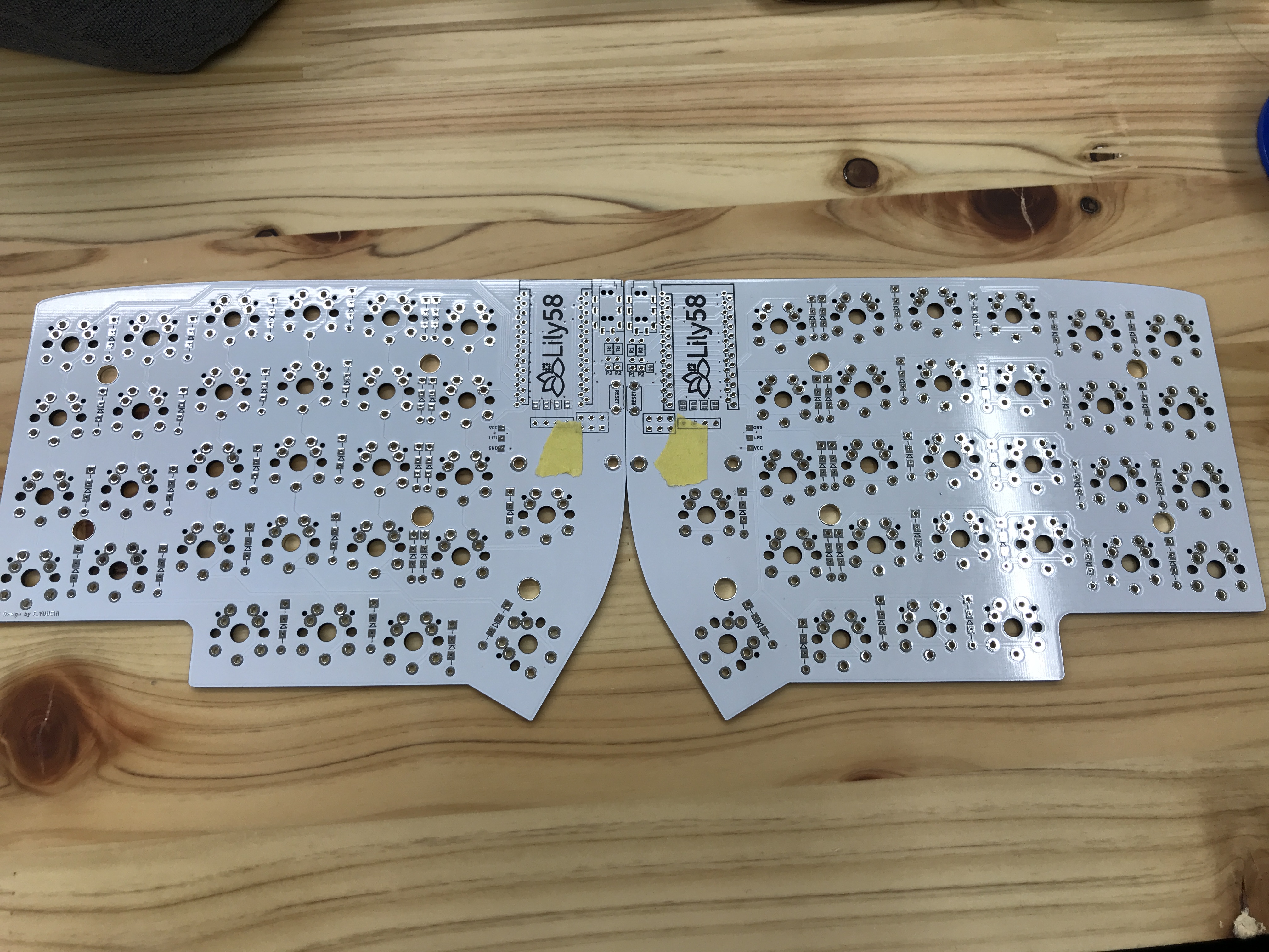
| Lily58 PCB | 2 pieces | |
| Lily58 Case | 1 Set | |
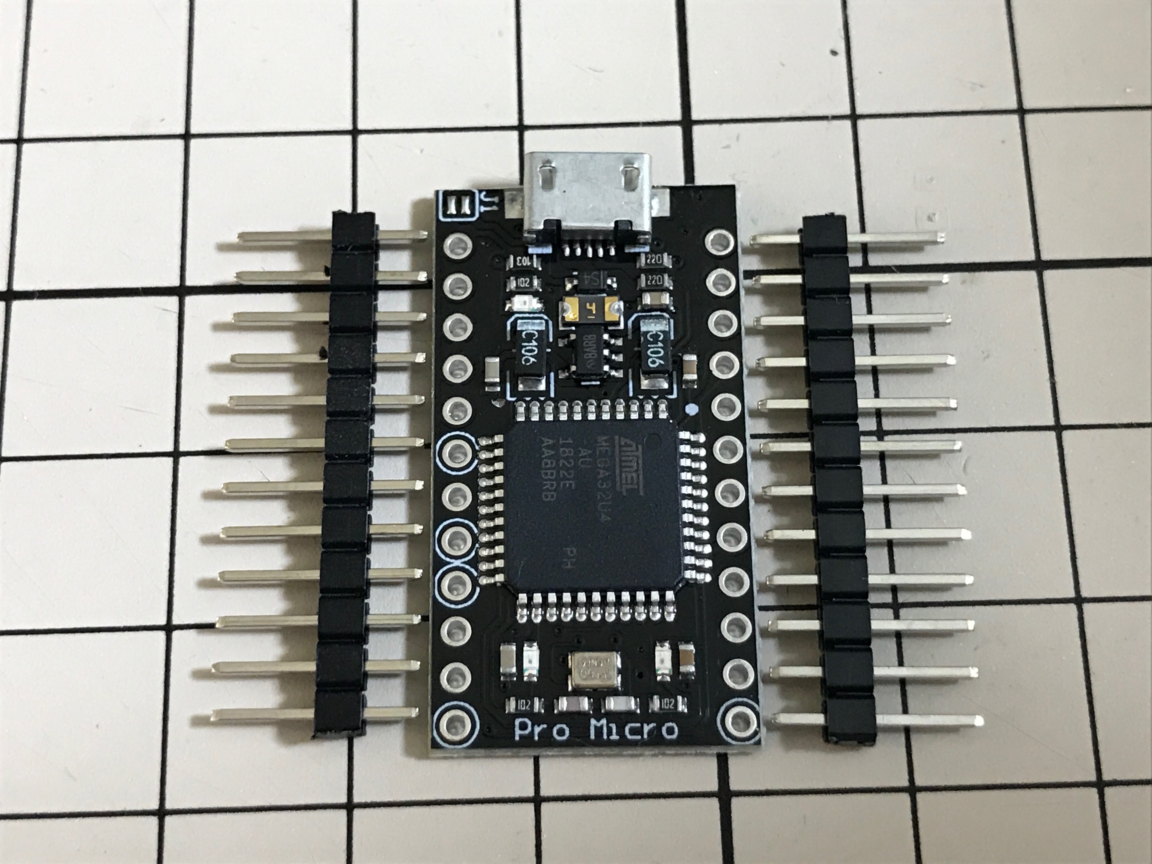
| Pro Micro | 2 pieces | It is advised to use Conthrough (sold separately) to reduce the amount of soldering and make easier to replace damaged connectors. |
| Key switch (CherryMX, PG1350) | 58 pcs (not compatible with ALPS switches) (*) | |
| Keycaps | 56x 1U keycaps, 2x 1.5U keycaps (*) | 1.5U keycaps can be replaced by 1U |
| Diode 1N4148 | 58 pieces | |
| Tact switch | 2 pieces | |
| TRRS Jack | 2 pieces | |
| M2 spacer 6mm, 10mm | 10 pcs, 4 pcs | |
| M2 screws 5mm | 28 pcs | |
| TRS (TRRS) cable | 1 piece | This is an audio cable called AUX cable |
| Micro USB / USB-C cable | 1 cable | You will need a Micro or USB-C cable depending on the USB connector of the Pro Micro MCUs. Magnet-type cable is advised to increase durability of the MCU USB connector. |
(*) Not included in the kit, you will have to source them yourself.
Diode Installation
The space between the plate and the PCB may be reduced when using low-profile switches. In this case it is advised to use [Surface mount diode (1N4148W)](http://akizukidenshi.com/catalog/g/gI- 07084/) (sold separately). If you use the provided through-hole diodes in combination with low-profile switches, try to minimize the protrusion of the soldering joints, e.g. clipping the diode legs before soldering them.
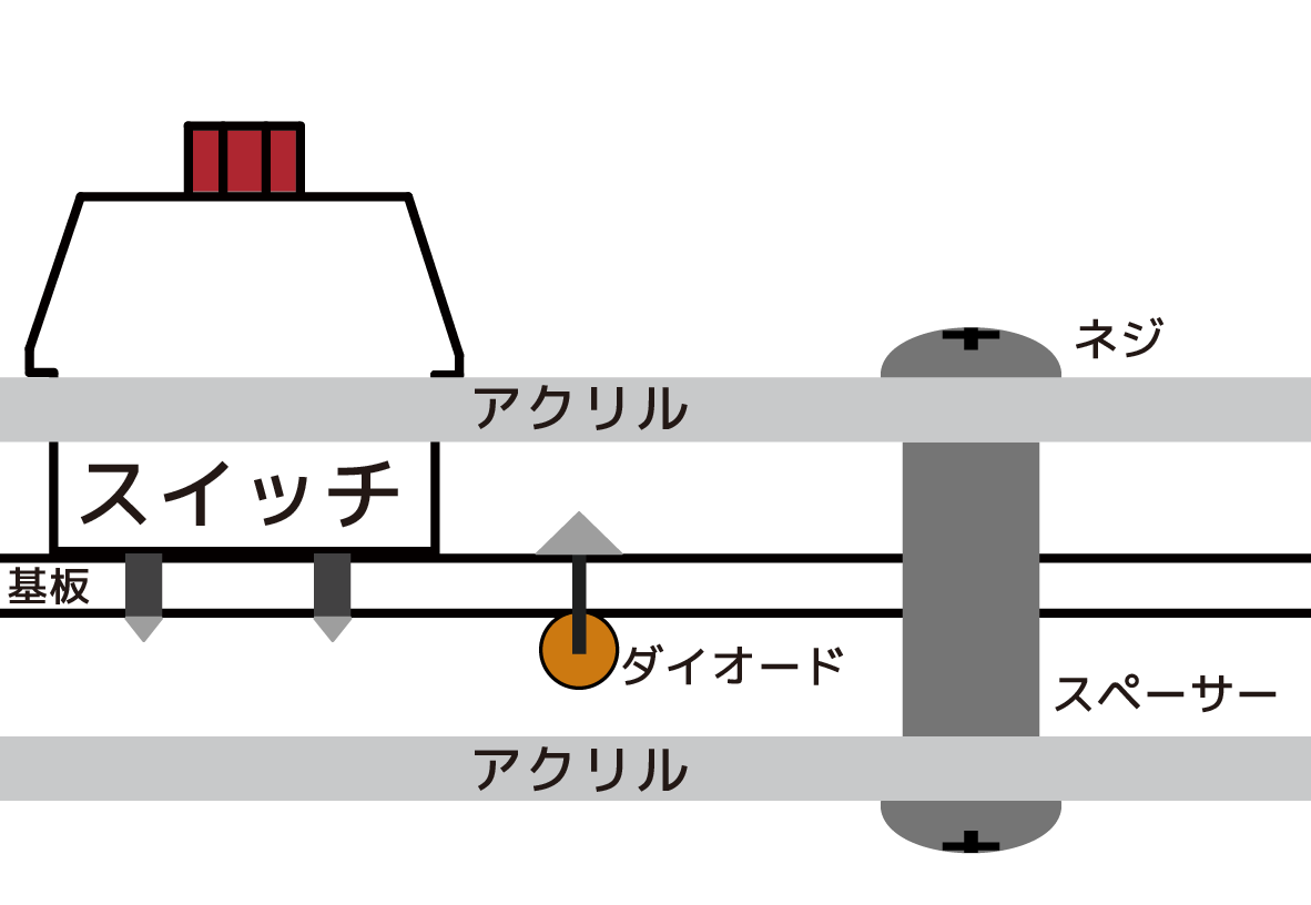
Since this PCB is reversible, we will mount the parts on one side at a time. We will consider the side on which the diode is mounted as the back side (represented in orange in the side-view diagram).
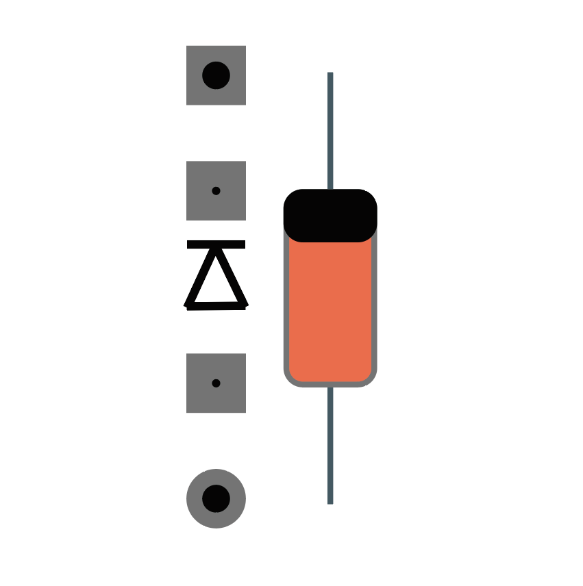
Side-view diagram:
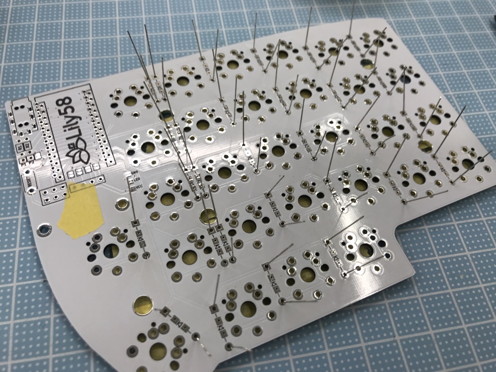
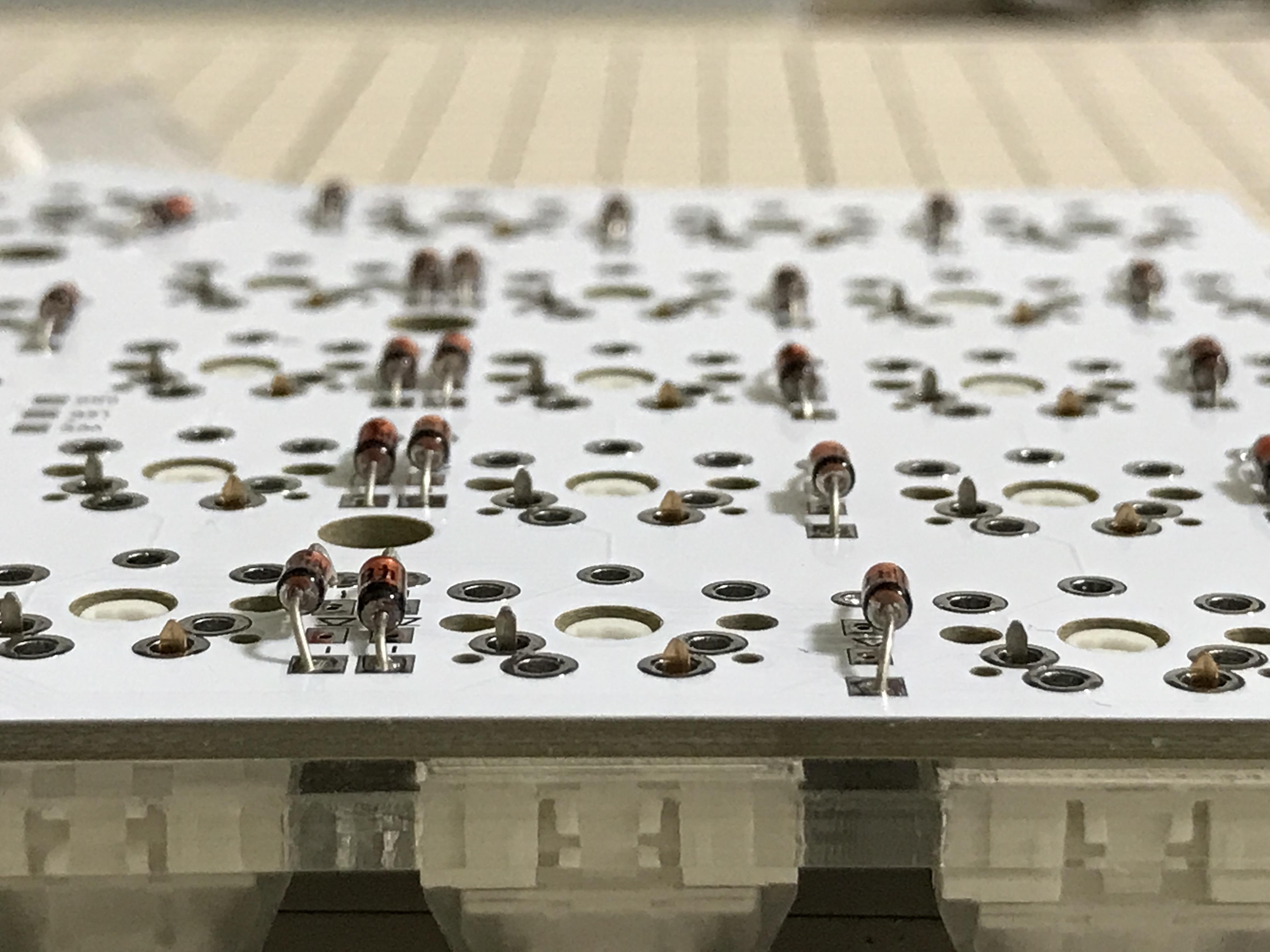
Bend the legs of the diode. You can easily bend the diode legs by pressing them against a stack made with the 3 Lily PCB layers.
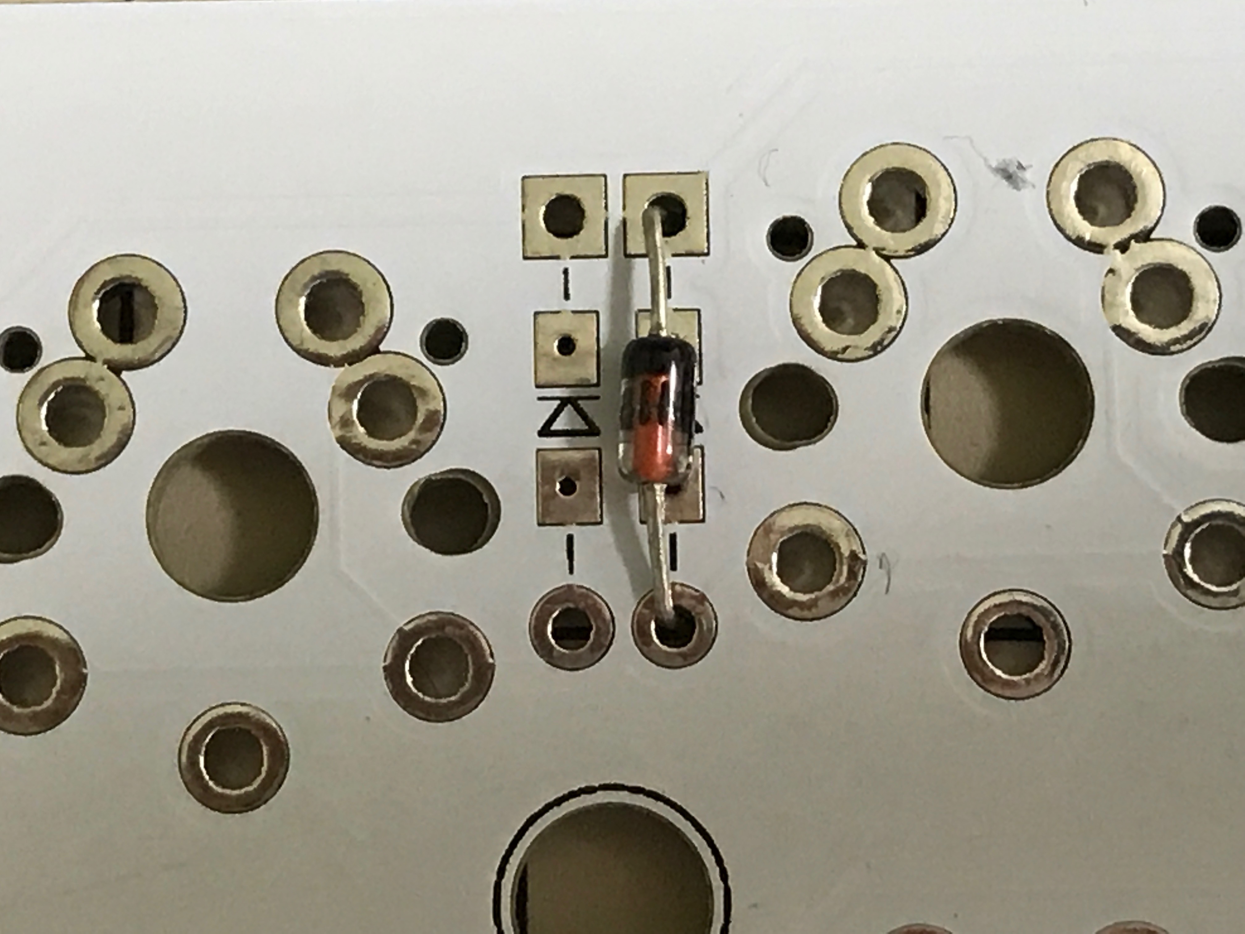
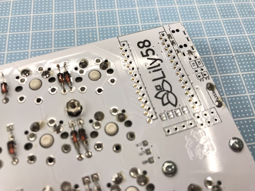
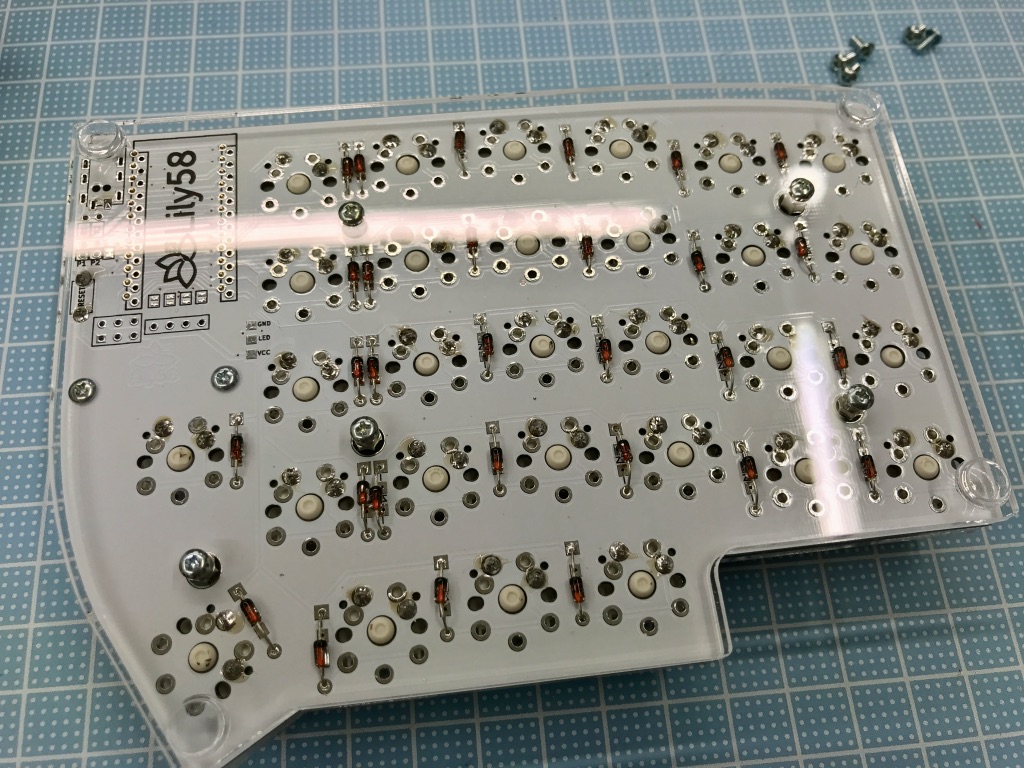
Once you bend the diodes, mount them on the back side of the PCB (opposite side where switches and Pro Micro are mounted). Diodes have a direction, check the notation on the PCB and insert them accordingly. The black band on the diode marks the diode cathode (the horizontal bar on top of the triangle that represents the diode, shown in the image below). If you solder a diode with wrong orientation the associated key will not work when pressed.
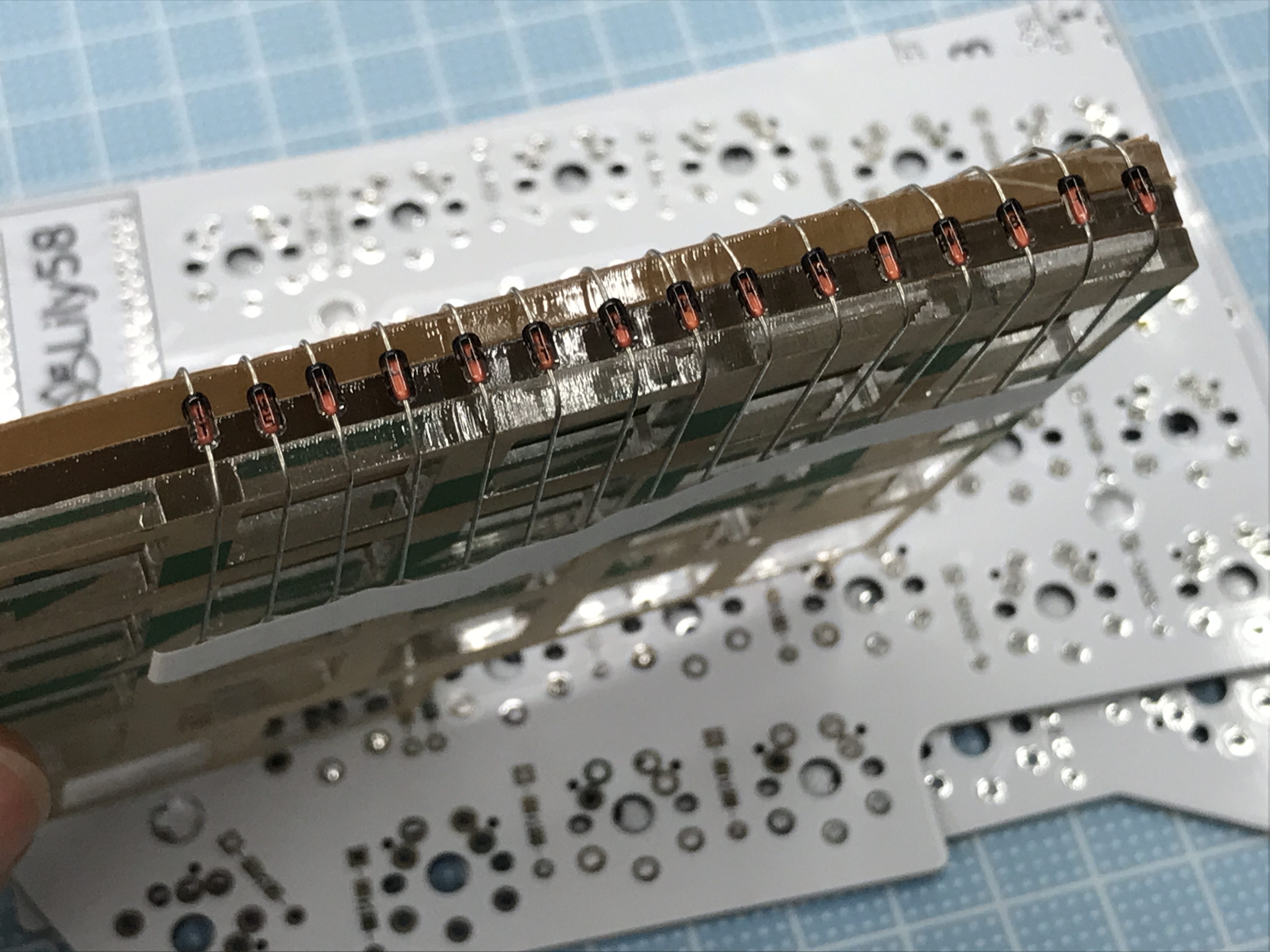
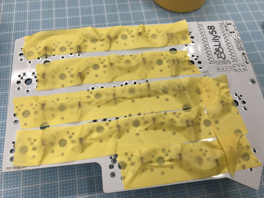
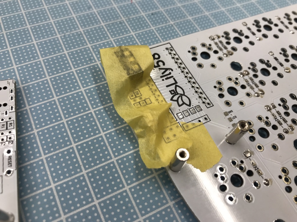
Use can use masking tape to temporarily keep the diodes in place and prevent them from falling when turning around the PCB to solder them.
Solder the diodes.
After soldering, cut the legs of the diodes using nippers. The legs tend to fly away when cut, hold them with your fingers to avoid this.
Once the diode legs are cut, install the 10mm spacers (long spacer).
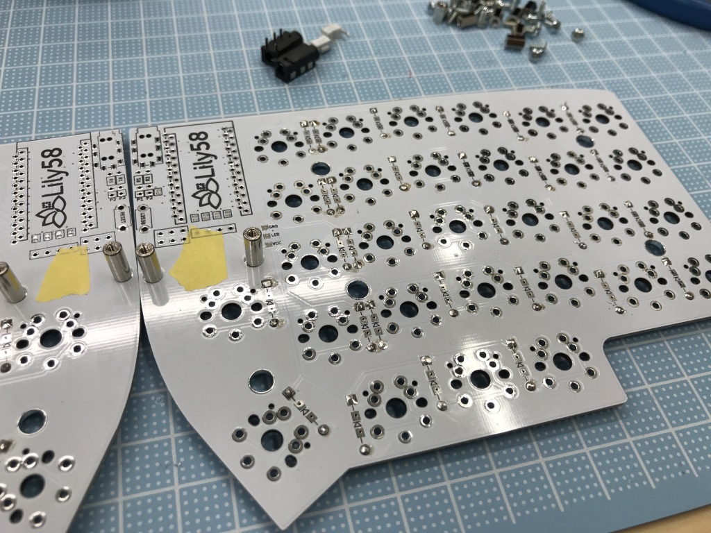
Solder the TRRS Jack and Reset Switch
Install the TRRS jack and tact switch on the top side of the PCB. Secure them with masking tape to prevent them from falling while soldering them.
Solder the TRRS jack and tact switch pins on the back side.
Solder OLED display (optional)
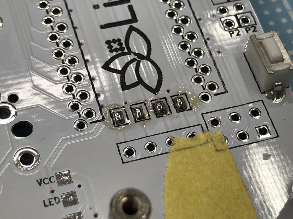
Enabling the OLED display requires bridging the 4 pads on the front side of the PCB, near the Pro Micro.
Solder the Pro Micro microcontroller
Using Conthrough pins (socketed microcontroller)
When using Conthrough pins together with the Pro Micro (socketed microcontroller), the pins are soldered to the microcontroller and the socket are soldered to the PCB. The pins of the Pro Micro are inserted into the PCB sockets without needing any soldering. Once installed, make sure microcontroller is firmly seated on the sockets.
Check Helix's Build Guide (JP) for further details.
Using supplied pins
Install the Pro Micro on the front side of the PCB. The short side of the pins are sldered to the Pro Micro MCU, the long side is soldered to the Lily58 PCB.
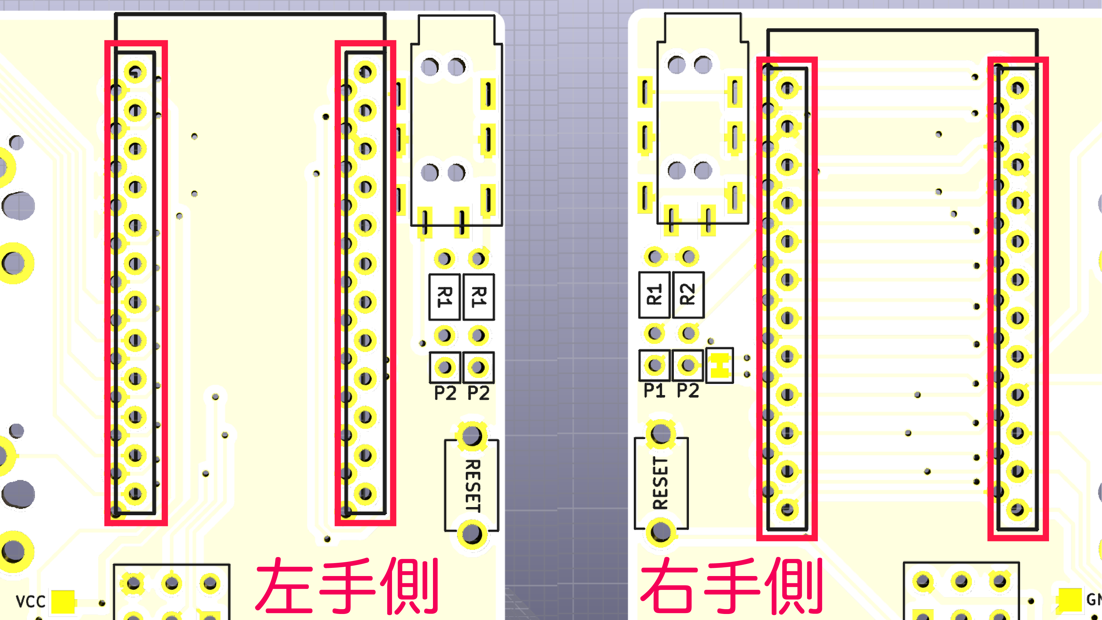
The long side of the pins go in the PCB holes marked by long rectangles (highlighted in red on the diagram).
The side of the Pro Micro with most of the integrated components faces down when properly installed on the PCB.
Solder the pins on the font side of the PCB (use masking tape if required to keep them in place)
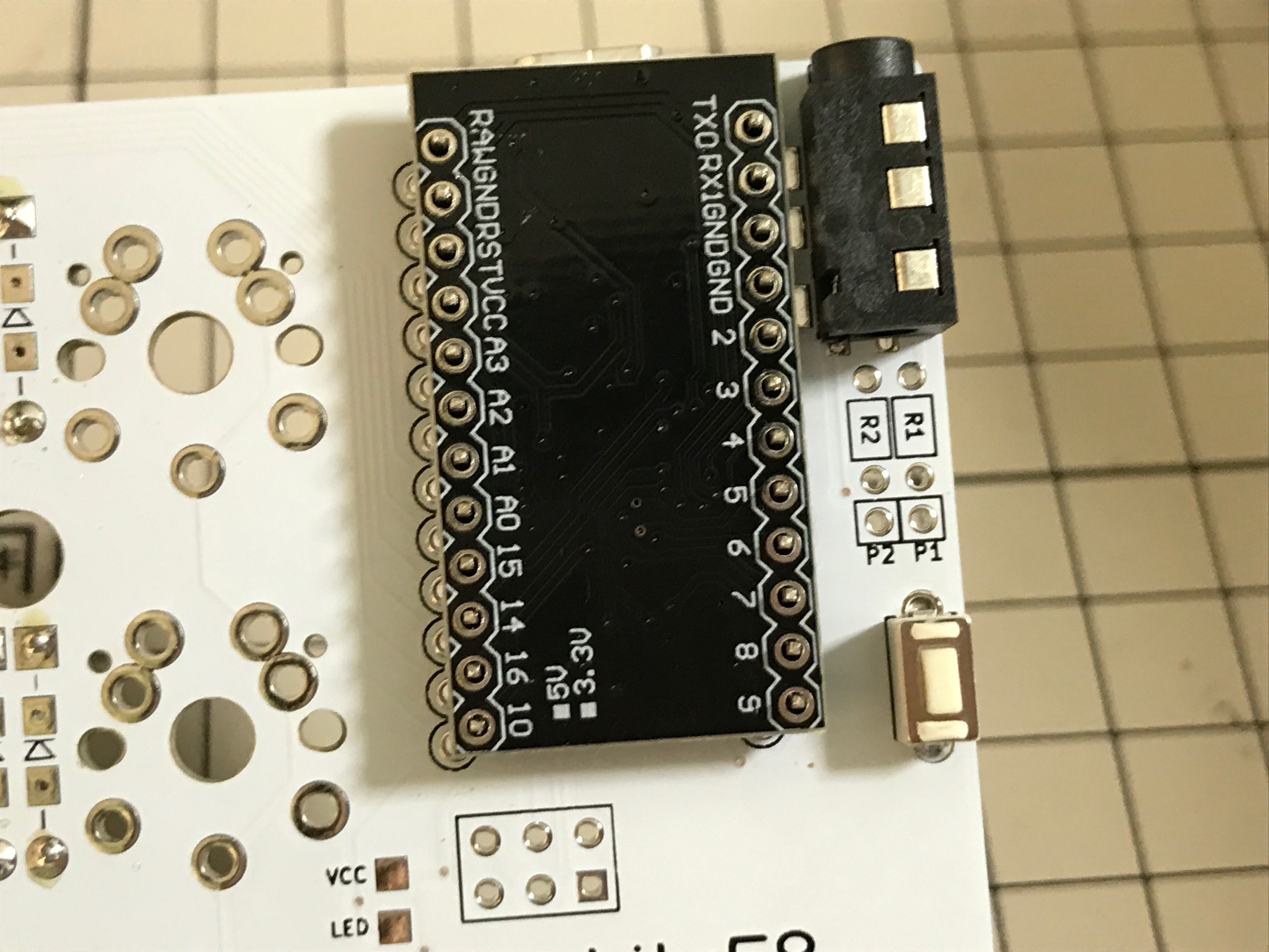
Once the pins are soldered, install the ProMicro (side with most components facing down), use some masking tape to keep it in place and solder it. When you are done, cut the pin excess with the nippers.
Install the switches
Fit the 4 spacers in the corresponding places of the top plate, add 4 key switches for extra stability, insert them in the PCB taking care to not bend their pins.
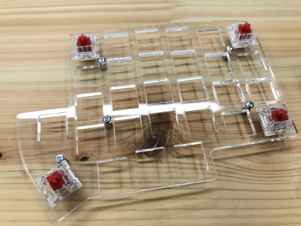
Check that the switches are properly inserted, they are not floating nor tilted, then solder them.
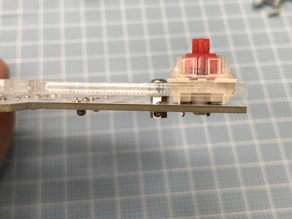
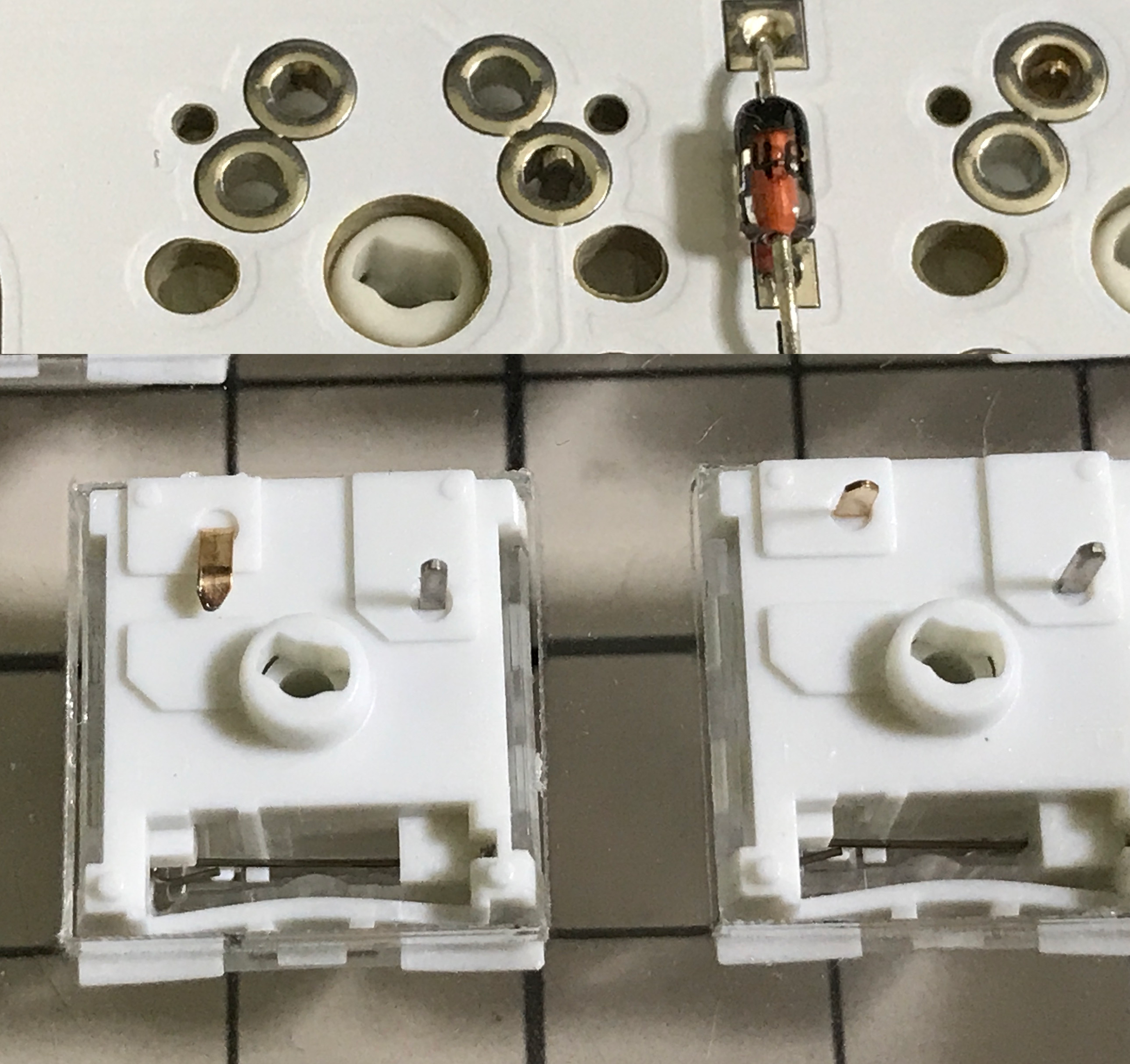
Install the rest of the switches in the top plate. If they are properly installed, their pins will stick out the PCB a little bit (see image below).
If a pin is bent or the switch is not properly inserted into the top plate, it will not stick out. In that case remove the affected switch and check it.
Install and solder all switches.
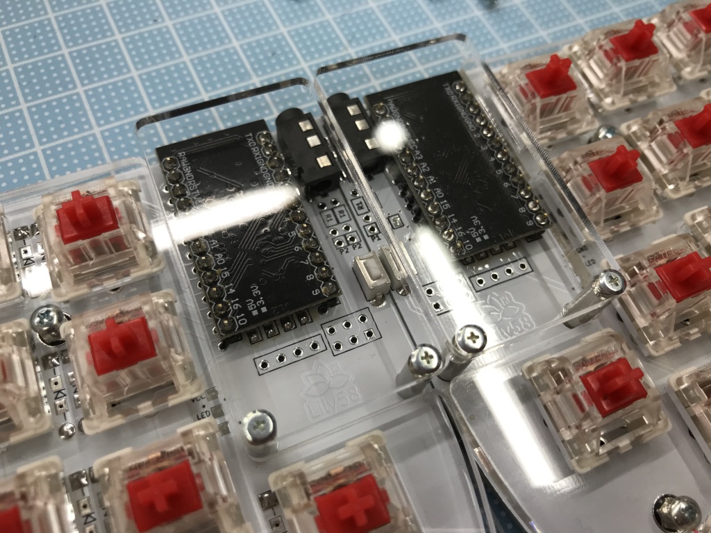
Install the cover for the Pro Micro
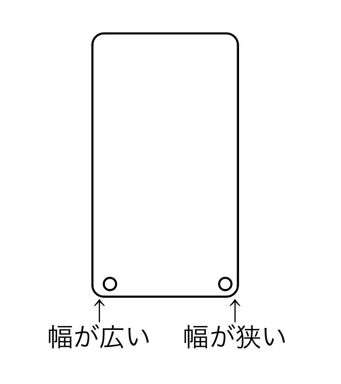
Attach the acrylic on top of the Pro Micro MCU, the wider side of the cover faces out, this is to the center of the split keyboard (see cover diagram).
Screw the cover using the flat head screws.
Configure and flash QMK firmware
Modifying and flashing a QMK keymap for the Lily58 requires a working QMK building environment, please check the QMK official documentation. If you are going to use the QMK Toolbox, there is no need to configure a building an environment, you can just define the keymap using the Toolbox GUI (keep in mind that the Toolbox cannot change the keymap).
The firmware flashing process requires the QMK firmware to be written in both microcontrollers of the Lily58 keyboard.
Once you have working build environment connect the first half of the keyboard to your computer. Compile and flash the default QMK keymap for Lily58 using the following command:
# instructions are for QMK release at the time of writing, 2022-12-06
qmk flash -kb lily58 -km default
Once the flashing process pauses and displays the message "Detecting USB port, reset your controller now...", press the reset button on the first half of the keyboard to proceed to write the firmware.
Now repeat the flash process for the second half of the keyboard.
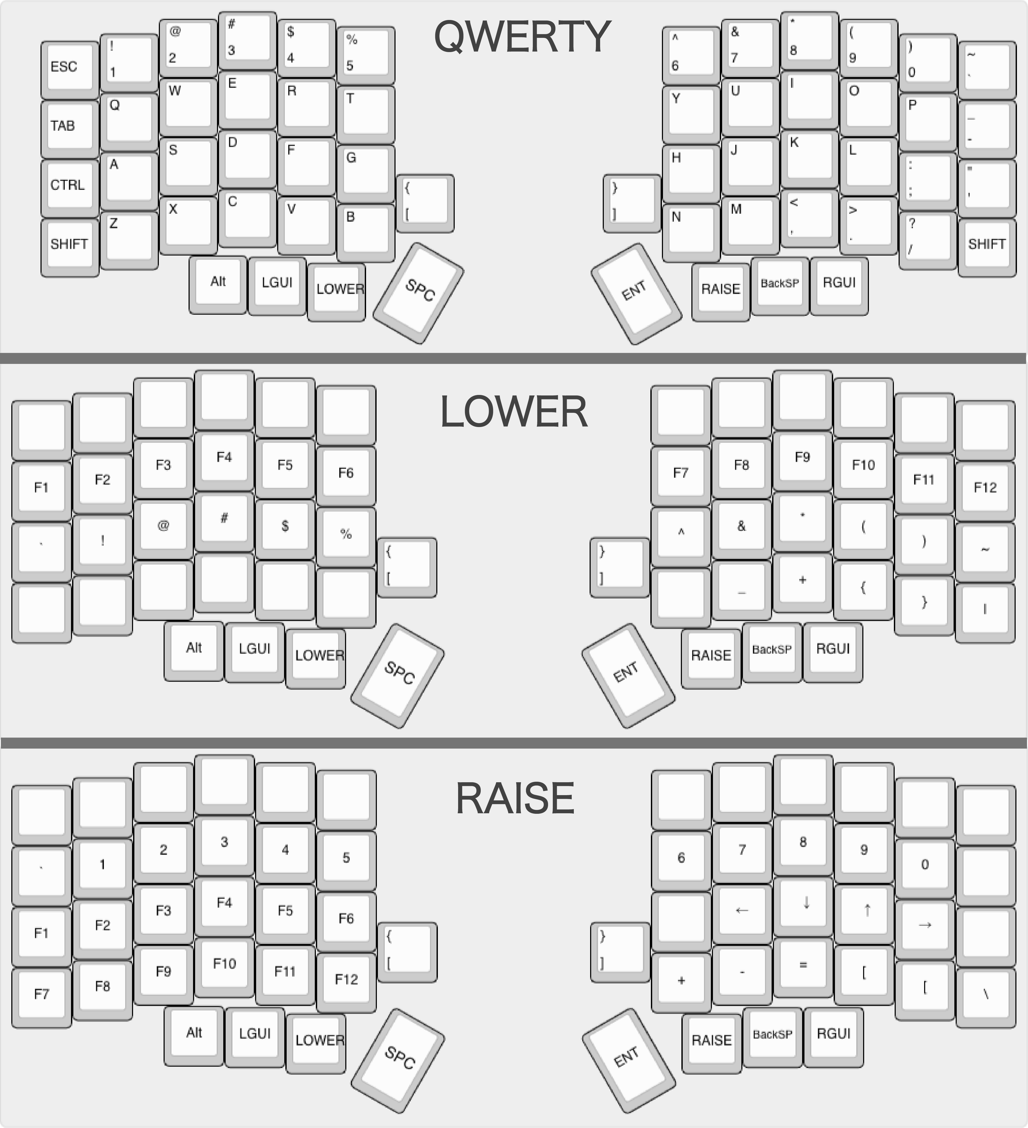
The Default keymap looks like this:
Testing
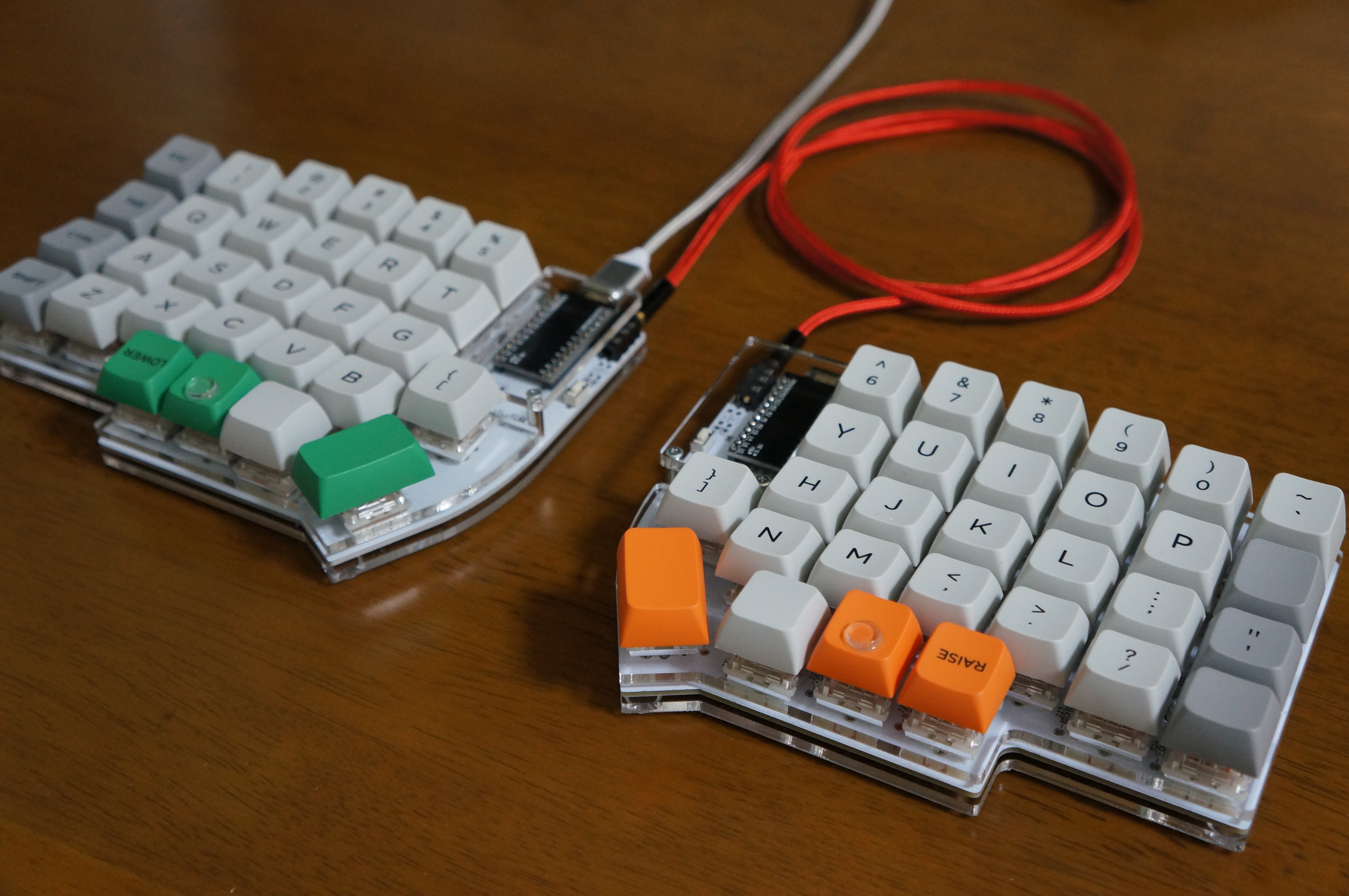
Connect the left and right parts of the keyboard connecting a TRS cable to the TRRS jacks, connect the MicroUSB cable to the Pro Micro on the left half of the keyboard (this is the half that connects to the PC in the default QMK keymap) and check if all the keys work as expected.
Complete the build by attaching 4 rubber feet on the back plate.
Congratulations for your hard work!
Troubleshooting
Q. One (or multiple) rows or columns of keys do not work
A. The Pro Micro microcontroller may not be properly soldered or inserted in the sockets. Check the microcontroller mount, re-solder and re-install it if required.
Q. A single switch does not work
A. There may be a problem with the switch itself or diode associated to it.
-
Key switch: check the pins of the switch to verify the soldering joints are fine. If there is not enough solder or you have a cold joint, reapply tin.
-
Diodes: check the diode has the right orientation. If the orientation is correct, try removing the diode and re-soldering it. If the amount of tin is not enough, re-solder properly.
If you encounter any other problem, feel free to send a message to the "#Lily58" channel on the Discord server Self-Made Keyboards in Japan or Twitter: @F_YUUCHI